Manual of Saiyin Joule Heating System
Show:0 Date:2023-03-12 12:39:49
1. Introduction
In 1840, James Prescott Joule submitted to the Royal Society a paper describing experimental research on the heat produced by electric currents in metallic conductors, and inferring that the effect was proportional to the resistance of the conductors and to the square of the intensity of the current. Recently, Prof. Liangbing Hu found the ultrafast Joule heating technology to make many new nanomaterials, such as some high entropy alloys, some stable single atoms, high-performance catalyst [Nature, 605, 470 (2022); Science, 359, 1489 (2018); Nature Nanotechnology, 14, 851 (2019)]. In 2020, Prof. James M. Tour found the flash Joule heating technology using high-voltage capacitors in laboratory, and made the gram-scale graphene in less than 1 second from various cheap carbon powder [Nature, 577, 647 (2020)], waste plastic, waste rubber, as well as many metastable phase materials.
Directed by Prof. Haigang Lu of Shanxi University, Taiyuan SaiYin New Material Co., Ltd. had developed the advanced Joule heating system: SaiYin Flash Joule Heating (SFJH) System, which includes the flash and ultrafast Joule heating functions as a whole. Up to now, there are many research groups to use this heating system to find many interesting nanomaterials.
2. Hardware
SaiYin Flash Joule Heating System has two models: FJH-2023A and FJH-2023B. The FJH-2023A system consists of three main components (Figure 1): an electric cabinet to produce a direct current (DC) by converting the commercial alternating current (AC) power supply, a vacuum box for the high-temperature Joule heating reaction, and a computer to record the voltage, current, and temperature per microsecond. In addition, there are a holder for tube, a holder for film, a vacuum pump, and some disposable materials, such as graphite paper, graphite disks, graphite felt, electrode rod, quartz tube, ceramic slabs. The FJH-2023B system has only the DC power discharging function, without the flash heating part and the computer. The specification of SFJH system is listed in Table 1.

A. FJH-2023A Flash Joule Heating System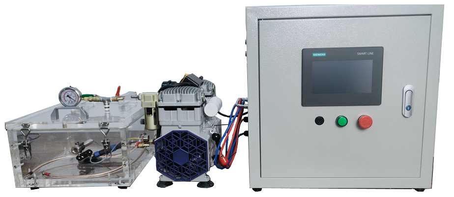
B. FJH-2023B Flash Joule Heating System
Figure 1. Hardware of SFJH Systems
Table 1. Product Specifications
Product Name | Saiyin Flash Joule Heating System | |
Model # | FJH-2023A | FJH-2023B |
Voltage Supply | 100~275V | |
Power | 3500W | |
Capacitor Capacity | 90mF | --- |
Capacitor Voltage | 0~300V | --- |
Capacitor Current | 0~600A | --- |
DC Power | 3000W (36Vx83A) | |
Temperature | 400~3600 ̊C | 400~2200 ̊C |
Weight | 110kg | 60kg |
Unit Dimensions W x D x H (mm) | 800x400x1500 | 600x400x900 |
Cabinet Dimensions W x D x H (mm) | 800x400x900 | 500x320x500 |
Vacuum Box Dimensions W x D x H (mm) | 400x400x300 | |
Power of Vacuum Pump | 1500W | |
Voltage of Vacuum Pump | 220V | |
Speed of Vacuum Pump | 150L/min | |
DAQ Computer | Windows Laptop | No (Only Built-in USB port) |
Notes:
1. The SFJH System includes two independent power systems (capacitor-group and DC discharging system) and a record system of voltage, current and temperature in per microsecond.
2. Vacuum reaction system includes a vacuum chamber, a tubular holder or flat holder, some quartz tubes, and a temperature sensor.
3. The temperature sensor is expensive and should be protected by a quartz disk to ensure its safety and cleanness, even if when the quartz tube explodes at high temperature.
4. When using the vacuum gauge for the first time, the black rubber block on the top should be opened and then closed to make the the internal pressure of the vacuum gauge equal to the local pressure.
3. Control Software
The SFJH system is mainly controlled by PLC programmable controllers. After plug in the power supply, turn on the air-break switch on the right side of the electric cabinet, and press the switch on the right side of the control panel, the SFJH system start and enter the main page (Figure 2).
Figure 2. Main Page
Clicking "Enter System" will enter the SFJH control page (Figure 3). The control page includes three zones: the top one is the switch zone of four heating (Flash-Heat, Step-Heat, Pulse-Heat, and Joint-Heat) and a monitor (Trends) page. The right zone control running program: “START” discharging, “STOP” program, “Discharge Capacitor” to clear the residual capacity of the capacitor, and “Detect Resistance” to test sample resistance. Main zone is the heating parameters to control and monitor the Joule heating program.
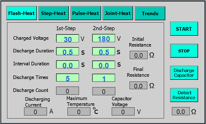
Figure 3. Flash-Heat Page
(1) Flash-Heat function: The flash Joule heating is to convert alternating current into direct current using switch power supply, and charge the capacitors, and then release the power in the capacitors instantly. This high power (up to 100kW) can heat the sample to the temperature of more than 3000 ̊C. The Flash-Heat page of SFJH system is shown in Figure 3, which shows an instance of flash Joule heating: the first stage of pre-treatment using 0.5 seconds capacitor discharging from 30V for five times, and the second stage of flash heating using 0.5 second capacitor discharging from 180V. In this instance, the carbon black sample can be heated to high temperature up to 3000 ̊C and convert into graphene. Table 2 lists the functions and means of its parameters.
Table 2. Functions and means of Flash-Heat page
Name | Function and mean | Range | Input? |
1st-Step | The first step of flash heating, which usually used to pre-treat the raw sample. | No | |
2nd-Step | The second step of flash heating, which usually used as flash heating sample to high temperature. | No | |
Charged Voltage | Charged voltage of capacitors. There is no energy in capacitors so that it must be charged before discharging. The capacitance of the capacitor is proportional to its voltage. | 0~300V | Yes |
Discharge Duration | Duration of capacitors discharging. When the sample resistance is very small (about 1 Ω), the capacitor usually discharge most of capacitance in 1 second, and the voltage will drop to several voltages. The minimum discharge duration should be 0.05 seconds. | 0~60s | Yes |
Interval Duration | Additional interval before discharging after being charged to the charged voltage. | 0-60s | Yes |
Discharge Times | Times of charging-discharging cycles, that can program to multi-discharging as required. The value of zero means stop charging-discharging cycle. | 0~60 | Yes |
Discharge Count | Count of charging-discharging cycles to monitor its process. | No | |
Initial Resistance | The resistance before discharging, which can be used to predict the heating temperature of the sample. | No | |
Final Resistance | The resistance after discharging, which shows the heating effect on sample, and can be used to predict next heating process. | No | |
Discharging Current | The maximum current of discharging | No | |
Maximum Temperature | The maximum temperature of sample during flash heating. | No | |
Capacitor Voltage | The real-time voltage of capacitors to monitor the charging-discharging process of capacitors. | No |
(2) Step-Heat function: Using the PID controller to adjust the discharging voltage, the step Joule heating can heat the sample and keep at a target temperature. The built-in DC power can heat the sample from 500 to 2200 ̊C, while the customized DC power can heat to more than 3000 ̊C. The step Joule heating instance is shown in Figure 4: firstly heat to 800 ̊C and keep 10 seconds, and then heat to 1500 ̊C to keep 20 seconds. Table 3 lists the functions or means of its parameters.
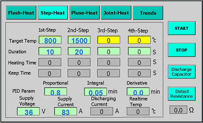
Figure 4. Step-Heat page
Table 3. Functions and means of Step-Heat function
Name | Function and mean | Range | Input? |
1st-, 2nd-, 3rd-, 4th- Step | The four heating steps of sample. | No | |
Target Temp | The target temperature of this step. The next-step value can be more or less than, but cannot equal with its value. | 500~ 3600 ̊C | Yes |
Duration | Duration at the target temperature. The value of zero will stop the heating. | 0~60s | Yes |
Heating Time | Timing the heating process to the target temperature. | No | |
Keep Time | Timing the heating process at the target temperature. | No | |
PID Param | SFJH system control the temperature using PID controller, and its three parameters are listed in the following. | No | |
Proportional | The proportional parameter of PID controller. The more its value, the faster of the heating and cooling speeds. | 0~100 | Yes |
Integral | The integral parameter (minute) of PID controller to adjust the fluctuation of temperature. The more its value, the faster of the adjustment of temperature. | 0~100min | Yes |
Derivative | The derivative parameter (minute) of PID controller to pre-adjust the fluctuation of temperature. | 0~100min | Yes |
Supply Voltage | The maximum voltage of DC power. If you change to another DC power, its value should be the maximum of that DC power. | 36V | Yes |
Supply Current | The maximum current of DC power. If you add another DC power, its value should be the maximum of that DC power. | 83A | Yes |
Discharging Current | The real-time current for heating, which can used to monitor if the heating process is running normally. | No | |
Real-time Temp | The current temperature of sample, which can used to monitor if the heating process is running normally. | No |
(3) Pulse-Heat function: The pulse Joule heating is just discharging many times in several seconds to thermal shock the solid materials into nanomaterials. The sample can be heated to 500 to 3000 ̊C in several seconds and cooled to low temperature successively. Figure 5 shows an instance of pulse Joule heating: firstly heating 1.0 second and cooling 3.0 seconds using 24V and 10A power for five times, and then heating 1.0 second and cooling 5.0 seconds using 36V and 80A power for three times. Table 4 lists the functions or means of its exclusive parameters except for those in Step-Heat page.
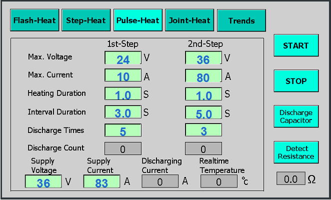
Figure 5. Pulse-Heat page
Table 4. Functions and means of Pulse-Heat function
Name | Function and mean | Range | Input? |
1st-, 2nd-Step | Two heating steps of sample. | No | |
Max. Voltage | The maximum voltage of DC power to limit the sample temperature. | 0~36V | Yes |
Max. Current | The maximum current of DC power to limit the sample temperature. | 0~83A | Yes |
Heating Duration | Duration of discharging. | 0~60s | Yes |
Interval Duration | Interval between two discharging. | 0-60s | Yes |
Discharge Times | Times of discharging, that can program to multi-discharging as required. The value of zero stop this heating step. | 0~60 | Yes |
Discharge Count | Count of discharging to monitor its heating process. | No |
(4) Joint-Heat function: The Joint-heat function is a combination of Step-Heat and Flash-Heat process. You can heat the sample to some temperature (such as 1000-2000 ̊C) and then heat it using the flash Joule heating by capacitor. Using the joint heating method, the sample can be heated to more than 3600 ̊C easily. Figure 6 shows an instance of joint Joule heating: firstly heat to 800 ̊C and keep 3 seconds, and then flash heat it 0.5 seconds using 180V capacitors. The functions or means of its parameters are shown in Table 2 and 3.
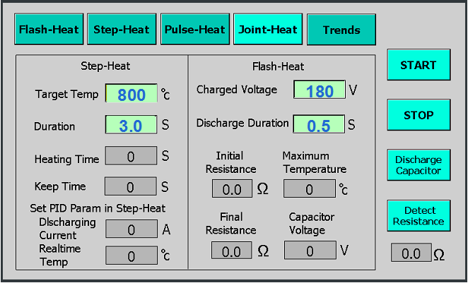
Figure 6. Joint-Heat page
(5) Trends function: The Trends page (Figure 7) shows the trends of current and temperature of sample during the Joule heating process. The data is only recorded at per second so that it is not enough to get the accurate temperature required by researchers. You should get the accurate data from the data acquisition software in computer.
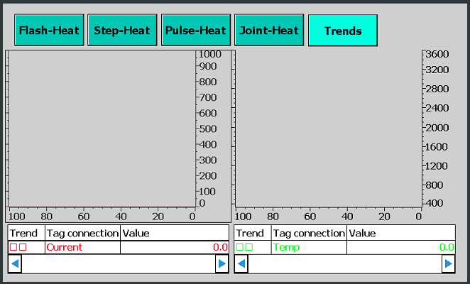
Figure 7. Trends page
4. Data acquisition program
To collect the accurate temperature, current, and voltage in per microsecond, SFJH system include a ART USB3100N data acquisition (DAQ) card and a windows computer. The driver of DAQ card and DAQ software can be downloaded from http://www.flash-heat.com (Manager software: http://file.sai-yin.com/file/daq.7z , Instruction video (chinese) http://file.sai-yin.com/file/install.mp4, and the DAQ software (Saiyin Data Acquisition System): http://file.sai-yin.com/file/SaiYinQAQ.zip. ) You need install the manager software, the driver of DAQ card, and Saiyin DAQ software: SaiYinDAQ, successively.
After connect the USB port of Windows computer to electric cabinet, we can run the SaiYinDAQ and its main page is shown in Figure 8. Table 5 and 6 lists the functions of every menus and buttons, respectively. The channels 0, 1, 2, and 3 record the signals of capacitor voltage, current, temperature, and DC power voltage, respectively. Their values Vsignal are from 0 to 10V and should be convert into their real values using the following formula:
I) For voltage: U(V) = (Vsignal /10)x500 (range: 0-500);
II) For current: I (A) = (Vsignal/10)x1000 (range: 0-1000A);
III) For temperature: T(̊C) = (Vsignal/10)x3200+400 (range: 400-3600̊C).
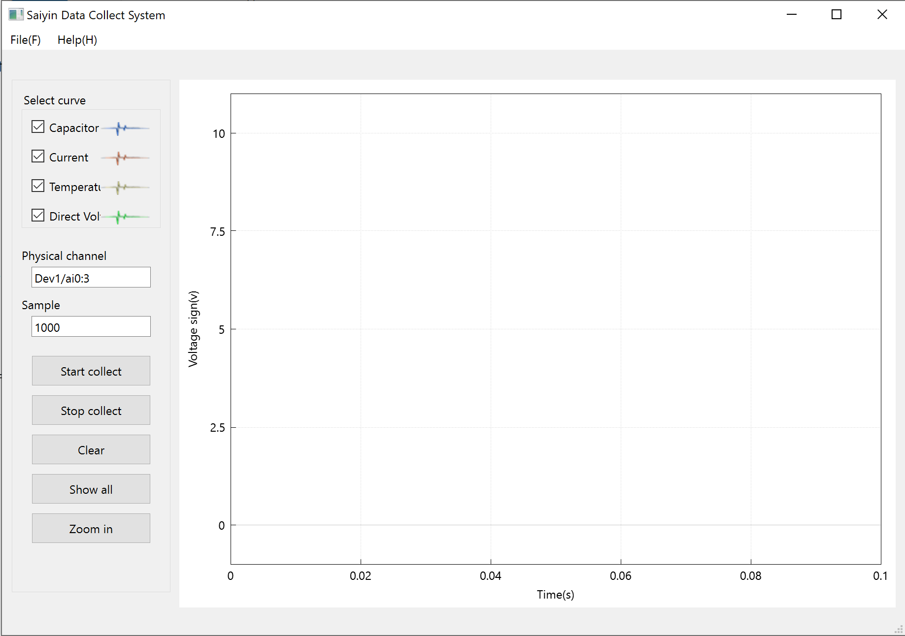
Figure 8. Main page of Saiyin DAQ system
Table 5. Functions of menus in Saiyin DAQ software
Name | Function |
File→Open | Open the previous record file and show its curves. |
File→Close | Close the curves and open a new window to record data. |
File→Save | Save the curves to a text file. |
File→Export | Export the curves to Excel data. |
File→Exit | Exit this program. |
Help→Website | Open the official website: http://www.flash-heat.com。 |
Help→About | Information on copyright and company. |
Table 6. Functions of buttons in Saiyin DAQ software
Name | Functions |
Select curve | Choose some curves from four curves to be shown in window. |
Physcial channel | Type the required physical channels, such as Dev1/ai0:3. |
Sample | Frequency to record the data per second. |
Start collect | Start or continue to record data. |
Stop collect | Pause to record data. |
Clear | Clear curves in window and get ready to next record. |
ShowAll | Show all curves in window. |
Zoom in | Show a selected part of curves. |
5. Instances of Joule heating
(1) For Conductor power
1. Preparation of the sample tube. If the sample is not powder, please cut it into small powders. Take a quartz tube with inner diameter 8mm and length 70mm, put a conductive plug into it from one end, and put 0.1g sample powder (such as carbon black) and another conductive plug from another end, successively. At last, we make a relatively closed sample tube. Generally, the length of the sample in the tube should be 5-10mm. Put the sample tube on Saiyin tube holder (Figure 9).
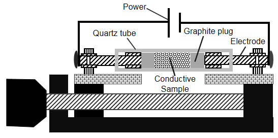
Figure 9. Holder for conductive sample powders
2. Adjustment of the resistance. Click the “Detect resistance” button, and adjust the length of sample to make its resistance decrease to about 1.0 Ω. Then click “Detecting resistance” button again to stop detection.
3. Preparation of the vacuum. Put the sample tube into the vacuum box, and adjust the temperature sensor point to the sample in tube. After closing the vacuum box, turn on the vacuum pump to get vacuum less than -0.93kpa.
4. Setup Joule heating program. Setup the parameters in the required heating page.
5. Run the Joule DAQ program in windows computer and begin to record the temperature data.
6. Start the Joule heating procedure by click “START” button, and the heating process will run according to the given program. The current and the temperature can also be monitored at the “Trends” page.
7. After heating process, take off the sample tube and push out the product.
(2) Non-conductive power
For the non-conductive power, you can use Saiyin tube-holder to put them on the graphite paper at the bottom of the quartz tube. The Joule heating will discharge through graphite paper to produce Joule heating and therefore to heat the non-conductive power sample (Figure 10).
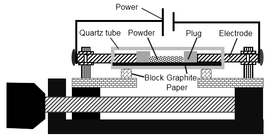
Figure 10. Holder for non-conductive sample powders
(3) Conductive film
For the conductive film, you can use Saiyin slab-holder to clamp the film on the graphite clips and discharge on the sample film to heat it using Joule heating system (Figure 11).
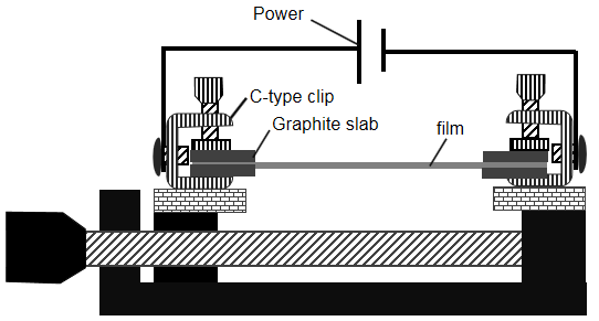
Figure 11. Holder for conductive sample film
(4) Non-Conductive film
For the Non-Conductive film, you can use Saiyin slab-holder to clamp two graphite papers on the graphite clips and put the sample film between the graphite papers and discharge on graphite paper to heat the in non-conductive film sample using Joule heating system (Figure 12). To support the graphite paper, you can add a ceramic slab or a graphite felt under the graphite paper.
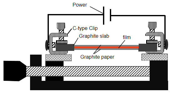
Figure 12. Holder for non-conductive sample film
6. Extensions of SFJH system
The standard SFJH system can meet most of Joule heating researches. To extend the function of SFJH system, there are built-in port to add some capacitors or use the alternative switch DC power.
(1) Additional capacitors: To add the capacitors to the SFJH system, you can buy some capacitors and connect into the wiring terminal in the electric cabinet from the extended power port. We provide the extended capacitor tank of 6x18mF. If need, please contact with us.
(2) Alternative DC power: If you need special DC power, we can provide DC power with different power, maximum voltage, and maximum current. After modified with an adjunct 0-10V control signal port, the alternative DC power can be connected the switch in electric cabinet and the signal port is connected to extended signal port on cabinet. At last, you need input the maximum voltage and current in the control panel to use it correctly.
7. Notes
The SFJH system has high voltage and is dangerous. And the high temperature of Joule heating also can burn the hand. Therefore, you should take care according to the following notes.
(1) After flash Joule Heating, the capacitors must be discharged in time through the "Discharge Capacitor" button on the control panel.
(2) Before repairing, keep the capacitor voltage is less than 0.5V.
(3) In power cut, if the capacitors have the residual power, you should open the front door of cabinet and turn on the “discharge Capacitor” manual switch to clear the capacitors to less than 0.5V, and then turn off it.
(4) Since the flash joule heating will heat the sample from room temperature to 3000̊C or higher, it must be pre-heated to release volatile matter (absorbed water, organic components with low boiling points, and so on) . The following two ways are suggested: (a) Use low voltage (such as 30-60V) to heat the sample about 5 times to evaporate water and volatile components of sample. The sample resistance may become smaller and smaller to ensure the subsequent high power flash heating. (2) Using the joint Joule heating, firstly you can heat the sample using fast Joule heating to 500 ~ 800̊C, and then heat it using flash Joule heating to temperature of more than 3000̊C.
(5) Try to heat the sample using the low voltage firstly to avoid explosion caused by excessive high power.
(6) Strong light could harm your eyes during Joule heating. Please protect you eyes by the glasses.
(7) In very high temperature, the quartz tube may explode. Pay attention to your safety.
(8) The vacuum box should be kept clean to avoid accident short circuit formed by the conductive powder.
(9) Notice the high temperature of sample just after Joule heating. Please operate the sample after cooled to room temperature.
(10) Wear thick rubber gloves when using the apparatus to protect from electrocution.
(11) The maximum discharging current is limited to 600A. Before discharging, the resistance will be detected and the discharging current will be predicted. If the predicted current is more than 600A, the discharging step will be suspend. You can decrease the capacitor voltage or increase the sample resistance to meet the current limit.
8. Service
Telephone: (86)-18610000351
Email: zgsyxcl@126.com
Website: https://www.flash--graphene.com/
Address: Shanxi University Sci-Tech Park 1021, Taiyuan, Shanxi, China 030006
Related ones:
- Manual of Saiyin Joule Heating System [2023-03-12]


